Lecture 1: Light
Properties of Light Relevant to Rendering
- Light travels in straight lines.
- This is not always true in reality, even for rendering. E.g., we can model objects with a gradient in the index of refraction which creates curved paths. And in broader physics, the more correct statement would be to say light follows geodesics through potentially curved space time. But, in practice, this is a simplifying assumption that is the basis of most of rendering.
- The irradiance of a surface (the amount of radiant flux hitting the surface per unit area) is…
- linear with light intensity.
- not linear with the size of the light.
- proportional to where is the distance from the surface to the light.
- i.e., the inverse square law
- This does not apply to infinite area lights, e.g., directional lights, environment lights (skybox), etc.
- proportional to , i.e., the dot product of the surface normal and the normalized vector from the surface to the light.
- At shallower angles, the light is more spread out, causing the illuminated surface to appear dimmer.
- Light’s intensity does not attenuate (at least without a participating medium that absorbs/scatters).
- If you look at a light through a pinhole right up close to the light, it will appear just as bright through that pinhole as it would if you looked through it farther away. Likewise, the intensity is also unaffected by the angle at which you look at the light.
More Complex Light Phenomena
The following properties of light are usually not included in most renderers.
- Flourescent materials which reflect light at a different wavelength than incident illumination.
- This would require your path tracer to integrate over more than just the standard RGB wavelengths!
- Polarized light
- Some more advanced renderers can account for multiple wavelengths and polarized light, e.g., Mitsuba.
- Light interference.
- Path tracing uses ray optics, aka geometric optics, which cannot model interference.
Modeling Incident Illumination
Consider the following equation that models the light arriving at a point on a surface :
- represents the integral is over the hemisphere with respect to the surface normal .
- is the light arriving at from (normalized) direction .
- is the angle of incident light at position , i.e.,
- represents an infinitesimal solid angle – basically saying “over all directions”
The solid angle represents the area of the projection of a surface onto the unit sphere. For a small surface patch , the corresponding solid angle is: where in this case is the dot product between the normalized vector from the point on the emitting surface to the recieving point and the normal vector of the emitting surface.
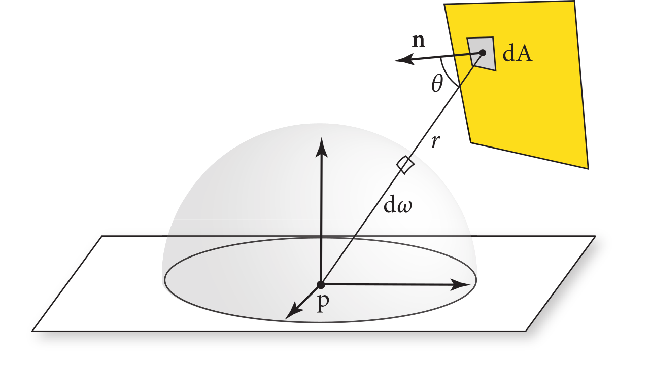
Therefore, the light arriving at a point (i.e., the point in the diagram above) from a light source with surface is:
where
- is the is the light arriving at point from light .
- represents the integral is taken over the surface of the light – not over the hemisphere!
- represents the light intensity at point from the surface.
- is the dot product between the normalized vector from to and the surface normal of the point being illuminated .
- is the dot product between the normalized vector from to and the surface normal of the light source .
- is the squared distance between and .
- represents the integral is being taken over small surface pathces of the light.
For more info, check out chapter 4 of PBR 4th edition, in particular, chapter 4.2.
Radiometric Quantities
- Radiant energy (Joules)
- Radiant flux / power (Watts, Joules per second)
- Radiant intensity (Watts per steradian)
- Irradiance (Incident flux per unit area)
- Radiant Exitance (Emitted flux per unit area)
- Radiosity (Emitted and reflected flux per unit area)
- Radiance (Flux per unit area per solid angle)
- Radiance per wavelength
Every radiometric quantity has a corresponding photometric quantity, which represents the percieved brightness instead of the physical brightness. For example, Luminance is the photometric quantity equivalent to Radiance. Often in rendering, we may need to account for the conversion between radiometric and photometric units. Gamma correction is one such case as our perception of brightness is not linear with intensity.
Cameras measure radiance – i.e., the amount of light hitting the surface area of each pixel over the solid angle ‘seen’ by the pixel.
Note, here the uses to account for the component – i.e., the amount of the surface area that is perpendicular to the light.
Bidirectional Reflectance Distribution Function (BRDF)
The BRDF represents how much light is reflected from a given direction to another given direction at a given position, and at which wavelengths.
The white furnace test for energy conservation says that a non-emissive material cannot create light, it can only absorb or reflect light. Therefore, if the incoming light at the surface of the material is , the integral of the BRDF over the surface must be .
Consider the BRDF for a perfectly diffuse surface. To pass the white furnace test, we set in equation 1 and compute the integral over the hemisphere using the Jacobian for spherical coordinates on the unit hemisphere :
Therefore, the BRDF for a perfectly white diffuse material is for all directions.